Throttle Pedal
Initial Designs and Concept Generation:
Initial design of the throttle pedal focuses on resolving cantilevers and broad idea generation of pedal orientation and spring system. The draft of idea is the figure below.

Diagram shows 4 main pedal shapes and their respective possible orientations. The spring includes tension, compression, and torsion springs to cover as many possibilities as possible. Seen after at the end of the diagram, “Compression > Tension > Torsion” is a supposed ranking between each spring type. A further analysis of for promising concept is shown below.

Notice that the compression spring has a piston attached to the spring to help it stay on the direct load path during motion. But I was willing to see how far the compression spring can go, thus, the 4th design is chosen for its simple design, requiring less material.
After the spring system is chosen, the pedal shape is closely studied to analyze their load angle, motion of travel, and stress distribution. Attached is a detailed sketch with a few labeling to outline the general area of concern.

On the top row, we can see the different pedal shapes and their stress concentration labeled with green and yellow ink. Green means desirable while yellow means undesirable. Through the process of generating ideas, the stress concentrations are by some simple testing and intuitive observation. Thus, the area of concentration might not be to the exact dimension and location. Nonetheless it is a good way of visualization.
Second row shows the range of motion, seeing how the angle of force applied and its relation to the pivot point and the driver’s foot. Note that the driver’s foot is assumed to be pressing horizontally through all scenarios.
These designs show an intuitive reasoning of distribution and the top concept is taken by combining a few of the aboved.
5’s arm, as it distributes stress over a wider area and avoids concentration by a curved surface.
3’s head, as it allows for a good angle of force throughout all the positions in the range of motion.
A complete version of the pedal is below:

However, the pedal is still very bulky. Thus, for weight optimization and stress optimization, we opt to conduct some topology optimization for best strength to weight ratio.
Assuming the scenarios in the load justification section, the force applied is perpendicular to the pedal head and the end of the petal to be fixed. Loading it into topology optimization gives the following:

Identifying the main features, the holes are very organic. The design will do its best to copy what is on the face; however, it is hard navigating around the bottom part of the pedal where there is a bulk of the material.
Note that the pillars you see in the middle is not a singular pillar, but a pair of supports on each side. The design simplifies the entire system down to one singular pillar for ease of manufacturing.
We can identify 3 layers, which will be useful for layout
Surface layer: the layer that remained the original thickness. Should not remove for its importance of structural stability
Support layer: the pillars connecting the top and the bottom of the pedal. Thinned down to one singular pilar instead of 2 separate.
Hole layer: material removed by the topology study. Unnecessary towards load distribution.
Modeling and Design:
From the last part of the initial design, we identified the general shape of the pedal. Transferring into model generates such.

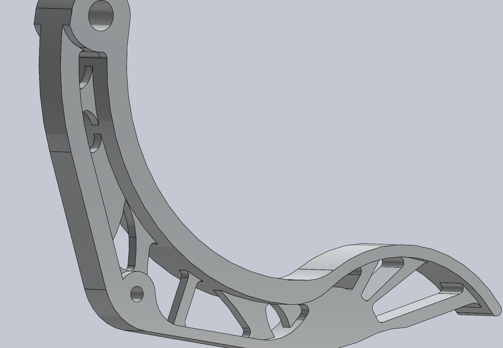
Note that the cut out closely resembles the organic holes. After some further modeling, a complete model of the throttle pedal is formed, Attached below.

Note that the model has 4 layers instead:
Top spin (Surface layer)
Back spine (New intermediate layer)
Rib (Support Layer)
Holes
The back spine is thinned for lighter support on the pedal. Since the forces are not enough to deform the pedal, the back spine is thinner to provide a better stiffness to weight ratio. A simulation returns safety factor plot.

The static testing returns a SOF of 2.2 using Al alloy 1160 and the weight of 0.2788 pounds. Seen in the figure, the stress is evenly distributed across the top spine and the back spine. The design follows previous speculation.